
A light fixture delivered with three wires (live, neutral, earth) connects to the ceiling wiring by following a conductor-by-conductor matching logic. Mastering the wiring of a light fixture with 3 wires requires checking each conductor individually, not just relying on colors.
Checking the conductors at the ceiling: do not rely on colors alone
In new installations compliant with the NF C 15-100 standard, the color code is reliable: brown or red for live, blue for neutral, green-yellow for earth. In renovations, this reference often falls short.
A blue wire reused as a live return in an old two-way switch setup is not uncommon. We recommend systematically testing each conductor with a VAT (voltage absence tester) or a multimeter, still under voltage, before turning off the circuit breaker to work.
The protocol is simple: identify the live wire by measuring voltage between each wire and earth, then between each wire and the presumed neutral. Note or mark the conductors with colored tape once identified. This step takes two minutes and prevents a short circuit on the first power-up.
Successfully completing the wiring of a light fixture with 3 wires primarily depends on this prior identification, especially in homes built before the 1990s where the wiring may have been modified without compliance.
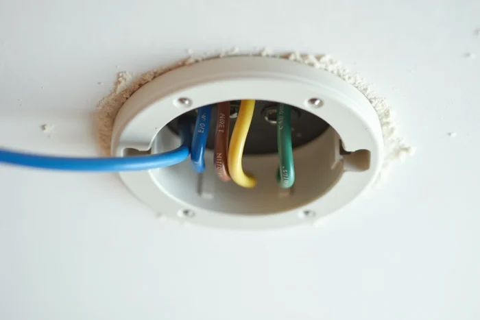
Connecting wire by wire: live, neutral, and earth of the fixture
Once the conductors are identified and the circuit breaker is turned off, the connection follows a precise order.
Connect the earth first
Connect the green-yellow wire of the fixture to the earth conductor of the ceiling. On a metallic fixture (brass pendant, steel ceiling light), the earth protects against any insulation fault. On a fixture entirely made of plastic or class II (double insulation), the earth wire from the ceiling remains isolated in a connector or individual wago, with no connection on the fixture side.
Live and neutral on the connector or terminal block
Connect the blue wire of the fixture to the neutral (blue in compliant installation) and the brown or black wire to the live conductor. Use connectors suitable for the wire gauge:
- Automatic terminals like Wago series 221 accept wire sizes from 0.5 to 4 mm² and allow for quick disconnection without tools, convenient for future replacement
- Classic screw terminals are suitable for identical sizes, but the tightening must be checked: a poorly tightened wire causes contact overheating
- Lever terminals with built-in continuity testing facilitate diagnostics, especially when the fixture is installed high and hard to access
Each conductor must be stripped to the exact length indicated by the connector, no more, no less. Exposed copper outside the connector poses a risk of accidental contact in the junction box (DCL).
DCL box and mounting: the point that tutorials overlook
Most recent ceilings feature an embedded DCL box (connection device for light fixtures). This box standardizes the connection and mechanical mounting of the fixture.
The fixture connects to the integrated female DCL plug in the canopy, which clips into the box. We often observe installations where the DCL box is present but unused: the wires come directly from the ceiling and the fixture hangs from a separate hook. This configuration works, but does not comply with current standards for new constructions.
If your ceiling does not have a DCL box, a connection terminal mounted in a junction box serves the same purpose. The junction box must be securely anchored to the ceiling (appropriate anchor for the support: concrete, drywall, wood) and sized to contain the connections without straining the wires.

Managing the weight of the fixture
The hook of the DCL box supports a limited weight. For a heavy suspension (multi-branch chandelier, glass fixture), check the load capacity of the box. Beyond the limit, additional mounting by a toggle hook in the ceiling or a plate screwed directly into the load-bearing structure becomes necessary.
Compatibility with modern controls: dimmer and wireless switch
The classic live-neutral-earth wiring works with a standard mechanical switch. Adding a dimmer or wireless switch modifies the constraints on the wiring side.
A wired dimmer is placed on the live circuit, between the switch and the fixture. The fixture must be compatible with dimming: non-dimmable LEDs flicker or blink on a dimmer. Check for the “dimmable” label on the bulb or the integrated driver of the fixture.
Wireless switches (like EnOcean or Zigbee) eliminate the need for wall wiring but require a receiver micromodule installed in the ceiling, in the DCL box, or nearby. This module connects in series on the live and communicates via radio frequency with the wall control. The live wire in the ceiling remains permanently powered, and it is the module that switches.
- Ensure that the volume of the DCL box or junction box can accommodate the micromodule in addition to the connectors
- Provide a permanent power supply at the light point (live + neutral always under voltage), which excludes setups where the switch cuts the neutral
- Test the pairing of the module with the control before closing the canopy of the fixture
This type of setup is becoming common in renovations where running a new wall cable would cost more than the module itself.
The reliability of a connection depends on three actions: identifying each conductor by measurement, using connectors suitable for the gauge, and checking for the absence of voltage before any manipulation. A properly wired fixture requires no further intervention throughout its lifespan.